Merging Displays from Multiple PI Thermal Imaging Cameras
Merging with PI Connect Software
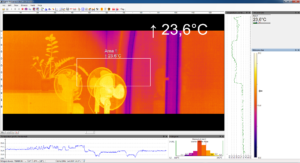
The PI Connect Software includes an important function which is the ability to merge the images from more than one PI Thermal Imaging Camera. The merging allows the user to display several cameras in one software instance. This is very helpful in a process where several cameras are installed has to be monitored using only one screen.
Advantages of camera merging
- If pixel size is getting too big, the use of multiple PIs is possible
- Simultaneous flag control and frame synchronization via PIF
- Measurement areas, hot and cold spots operate for the whole merged IR imager
- Different camera positions allow having various viewing angles for a complete view of a 3D object
- After merging setup and restart of the PI Connect Software the source instances will open automatically
Generally there are two ways to realise a merged image. On the one hand you can connect the cameras directly to your computer via USB Port (recommended for no more than 2 or 3 cameras) and on the other hand via an Ethernet network (recommended for more than 3 cameras). Using the direct connection it is important to have several USB controllers at your PC. You can find this information under the windows control panel, Device Manager and USB controller. One PI camera should be connected to one USB controller.
Merging set up under PI Connect
1. Open the PI Connect Software having connected all of the cameras.
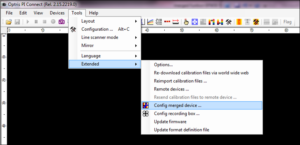
2. Go to Tools, Extended and Config merged device. A message will show up that the device will be interrupted. Press OK and the Imager Merger Configuration window will open.
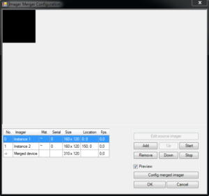
3. Click on Add for the number of cameras you want to use for the merging.
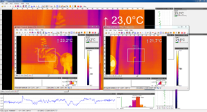
4. To start the individual instances select each single instance one after another and press the Start button. All windows will open for the different instances.
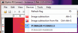
5. Go to each Instance window and select under menu Devices the camera that you want to use and under Tools, Configuration, Device and Application Start assign each camera to an instance.
6. There are two possibilities to configure the layout of the whole picture:
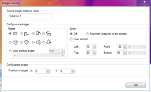
a. Go to the Imager Merger Configuration and select the instances one by one and click on Edit Source imager. The Imager Config window will open and here you can define the Position of the instance in the merged image. It is recommended to do a slight overlapping of the images (up to 5 pixels) in order to have a smooth transition between the images. Repeat that for all instances.
b. You also can change the position, size and rotation of the different instances windows directly in the Config merged device window (starting from PI Connect software version 2.15.2222.0).
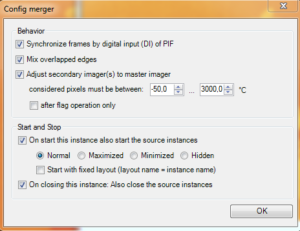
7. Press OK and you’re finished with the general set up and receive a merged picture in the main window. It is important is to run the source instances in the background. They can also run in hidden mode (see Config merged imager)
Figure 1: Merging set up with PI Connect Software (1.&2.)
Figure 2 Imager Merger Configuration – Adding and Starting Instances (3. & 4.)
Figure 3 Individual Instance Windows (4.)
Figure 4: Assign a dedicated camera to an Instance (5.)
Figure 5: Configuration of the merged image (6a.)
Figure 6: Manual size arrangement (6b.)
Figure 7: Final Merging Picture (7.)
Figure 8: Config merged imager (7.)
A detailed description for the entire set up is explained in the PI Connect Software Manual.
Connection via a GigE Ethernet network
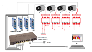
The set up for the merging is made via a GigE Ethernet network. Therefore the cameras are connected to the USB Server Gigabit and those in turn are each plugged to an Ethernet Switch. Finally you have the connection from the switch to your PC.
Hardware and Software Recommendation:
- Computer (e.g. Intel Core i7-6700HQ, 16GB RAM, 256GB SSD) with OS Windows 7 or higher
- optris PI camera and PI Connect software version 2.15.2219.0 or higher
- Mandatory the use of the USB Server Gigabit (Part No.: ACPIUSBSGB). The use of other USB server is not supported and might not work properly!
- Managed Gigabit Ethernet switch (Netgear GS110TP)
Figure 9 Connection of 4 PI cameras via a network of 4 USB Server Gigabit and 1 Ethernet Switch
Simultaneous flag control and frame synchronisation via PIF
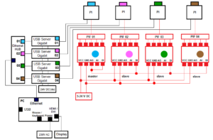
For simultaneous flag control and frame synchronisation, use the PIF connection from the PI camera. You can chose between the standard PIF and the industrial PIF depending on how many in- and outputs you want to use. In our example, the standard PIF is used. One camera will be chosen as the master and the others are the slaves. Please connect the digital input with the analogue output of the master PIF and from the analogue output you connect all digital inputs of the slaves as shown in Figure 10 below.
Figure 10 PIF Connection
After finishing the hardware you have to set up the configuration in the PI Connect Software. Therefore go to menu Tools, Configuration and Device (PIF) in each window of the individual instances. For the master PIF go under Analog Outputs and AO1 and select Flag Status. The other PIFs are the slaves and there you have to go to Digital Input, DI and choose Flag Control.
Figure 11 Flag Control
This article is intended as a guide and does not replace our own free technical assistance which is always readily available.
For further information please email sales@processparameters.co.uk or call 01628 778788.


